

This outline on stability is based on "The Safety of Small Commercial Sailing Vessels" A Code of Practice, which emphasises the point of vanishing stability as THE MAJOR INDICATOR of a yachts ability to resist capsize. We are not attempting to address other issues relating to stability in this section.
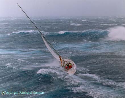
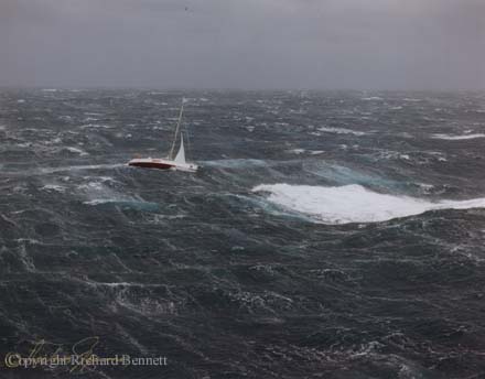
The 1998 Sydney-Hobart Yacht Race gave a very clear example of weather conditions, where the stability of a yacht becomes an issue. These photos show one of my designs in these severe conditions and the large breaking waves associated with this storm.
The yacht "Aspect Computing" is 16m L.O.A. (54ft) with a 3m draft (9'10") lifting bulb keel and a point of vanishing stability of approximately 140deg.
"Aspect Computing" sailed through the storm and finished the race taking first in Division 1 Performance Handicap. Photos: copyright Richard Bennett.
"The Safety of Small Commercial Sailing Vessels" A Code of Practice (referred to as the Code of Practice in this discussion) is based on work undertaken by the Wolfson Unit and sponsored by the U.K. Department of Transport, to develop stability criteria appropriate for the safe operation of sailing vessels. Much of the research was undertaken so that the master of a sailing vessel could measure his vulnerablity to downflooding in gusts and downflooding in squalls based on a calculated maximum steady heel angle, which we will not go into here.
Part of the research and subsequent code specifies a minimum range of stablity for a given size of yacht and a method of estimating the range of stability for yachts under 15m. The research undertaken at the Wolfson Unit indicates ... "that the most important characteristic for survival of a breaking wave capsize is a large range of stability, since vessels with low ranges are prone to remaining inverted following such an incident. Furthermore, the vessels most vulnerable to such a capsize are wide, shallow, light hulls, and these characteristics normally go hand in hand with a relatively low range of stability. It is likely therefore, that a vessel with a low range will be more likely to capsize and less likely to self-right than one with a large range of stability. A high roll inertia is of benefit in reducing capsize vulnerability but is difficult to calculate or measure and so has not been incorporated in the standards.
The larger the wave encountered, the more likely is the capsize, so smaller vessels have a higher probability of capsize. To maintain a more even probability of capsize the standards require a greater range of stability for smaller yachts" ... - From paper by B.Deakin B.Sc.,C.Eng - given to The Royal Institution of Naval Architects.
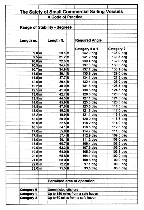
The following list shows the minimum range of stability required for a given size of yacht between 9 and 23m and clearly shows the smaller the yacht, the higher the angle required. The figures for Category 0 are those applicable to offshore cruising yachts.
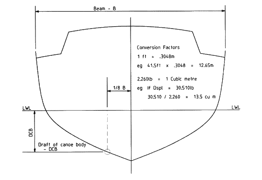
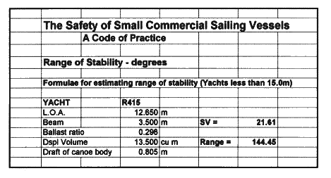
The range of positive stability for a vessel fitted with an external ballast keel may be estimated from the following formulae:
| Estimated Range = | 110 + ( 400 / ( SV - 10.0 ) ) |
| SV = | Beam^2 / ( BR x DCB x (Displaced Vol )^1/3 ) |
| BEAM = | Greatest Beam Measured (excluding rubbing strips) - in Metres |
| Ballast Ratio (BR) = | Weight of Ballast in Tonnes contained in the Keel, divided by the Full Displacement in Tonnes |
| Displacement Volume = | The Volume of a Vessel's Displacement in cubic metres, at the Operational Draft |
| Draft of Canoe Body (DCB) = | In Metres, is taken by measuring the Maximum Draft at the 1/8 of the Full Beam from the Centreline in way of the Transverse Section at Greatest Beam |
If a vessel under 15m (50ft) is fitted with more than one of the following:
then the Code of Practice requires that ... the centre of gravity of a vessel should be established by an inclination experiment and, in addition, a curve of static stability (GZ Curve) for the loaded departure, 100% consumables, should be produced.
The above formulae for estimating the range of positive stability should be treated as an "estimate only" as it is possible to have yachts which do not meet the minimum required standard for range of stability, based in the formulae used, but comfortably meet the minimum standards when an inclination experiment is conducted.
An example of this is the R12.2m - DSN#26, which, using the formulae, has an estimated range of stability of 118-120 deg, but when the VCG is established using an inclination experiment then the range of stability is approximately 139-150deg, depending on loadings - see example curves below.
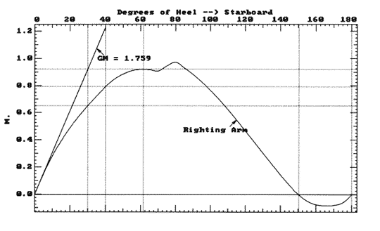
The following 2 stability curves of the R12.2m DSN#26 "Red Jacket" give examples of the variations in righting arms and points of vanishing stability (PVS) which can occur with different vertical centres of gravity (VCG).
This lift bulb keel racing yacht had an inclination experiment conducted, with the yacht in measured condition i.e. no loading, and the VCG of the yacht was established. The first curve shows the yacht with keel fully down in its unloaded condition. The bulb keel arrangement gives a very low VCG for the ballast.
The second curve shows the yacht loaded with all of the crew weight and gear weight for racing located at deck HEIGHT and on centre line. The PVS is still 139.2 deg with keel fully down.
 |
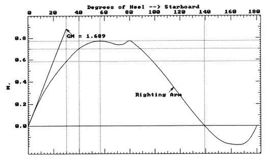 | |
| 2.8m lifting bulb keel - VCG 256mm below DWL - PVS 150.2 deg - In measured lightship condition | 2.8m lifting bulb keel - VCG 60mm below DWL - PVS 139.2 deg - All crew weight and gear weight on deck and on centreline |
We use BHSY software from Creative Systems to analyse the stability of the designs, considering the changes in the vertical centre of gravity and the effect this has on the over all stability of the yachts. A complete 3D computer model of the yacht is created ... including hull, keel, rudder, deck, house and cockpit. In the design process, before a boat is even built, calculations are made to estimate the vertical centre of gravity (VCG) and then initial hydrostatics details are run to make sure the design meets a reasonable standard. Boats which have been launched can have an inclination test done to establish the vertical centre of gravity of a yacht for a known loading and a known displacement. This information is used in BHSY, in conjunction with the 3D computer model, to establish the righting arms at regular intervals between 0 and 180 deg. The maximum righting arm is established, the righting arm curve is defined, as well as the point of vanishing stability as shown in the curves above.